Tuesday, May 31, 2016

Dodge 218 Truck to T5 conversion...


So , the Dodge 218/230 truck T5 conversions are actually relatively simple to do.  I normally do not make these parts but I might start if there is enough of an interest.

The truck bellhousings actually have enough material where they can be redrilled for the T5 bolt pattern.  What's nice is that because of their overall length, there isn't a need for any adapter or special made clutch disc.  However, there still are several issues that need to be addressed.

The register hole on the bellhousing is 4-3/4" diameter where as the register diameter on the T5 is 4-11/16".  A simple ring is needed that presses onto the register of the T5 to make if 4-3/4" diameter.


You can see that on the one side, there is a slight lip.  This lip fits into the chamfer on the bellhousing hole and prevents the ring from coming off.

The next issue is the pilot bearing.  To provide adequate support to the T5's input shaft, the pilot bearing has to stick out from the back of the crank a bit.


Another issue is that on some of the bolt patterns drilled into the stock truck bellhousing, the upper driver's side hole interferes withe the T5's hole.  So, the easiest way to address this is to take a bolt and thread it in until is tightens up. Then, cut it off, grind flush and stake it so that it can not back out.  Very carefully, drill and tap the new hole.


The last issue to address is to machine a collar to press into the original release bearing.  This reduces the ID so that the release bearing will properly ride on the T5's bearing retainer.


Dodge 218 supercharger mounting...

As I try to finish up some of the long term projects I have going on, I was able to devote sometime the the belt tensioner on the Graham Super Charger mounts.

The only belt I had was a little long so don't mind the zip tie...


Let there be lights....

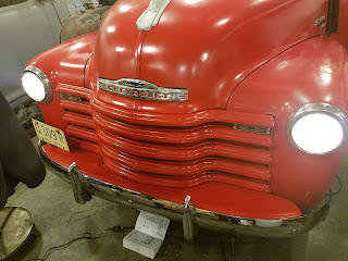
Over the Holiday weekend, I was able to finish up at least the front half of the Ohio State truck...

It's always a good feeling when the lights work again....


Tuesday, May 24, 2016

Tidying up...

As I was finishing the connections up the hood, the fuel and vacuum lines kept catching my eye.  I just couldn't leave them alone...so....I ended up redoing them.

Before:


After:


I also had to address the temp and oil lines as well as the choke cable.  I don't quite know what to do with the speedo cable yet though...


Thursday, May 19, 2016

Wiring progress...

As I began making the connections under the hood, I needed to do something with the wires exiting the firewall.  In the past, I've seen on early Fords a dished out metal cover that hides the hole in the firewall and acts somewhat like a clamp for the wires.  I always thought that was an elegant idea so, I wanted to use it on this project.

Here is the finished cover, installed:


I should have taken more pictures of the the start of forming, but I pretty much just started hitting a scrap piece of 20ga. between the open jaws of the vise with a ball peen hammer...not to exciting really.  To form the exit of the wireway, I used a piece of round bar stock as a form and again, hit it with a hammer while I had the piece positioned between the open jaws of the vice.  The vice jaws acted like the female dies of a mold and gave me that "crisp" edge.


So yeah, it looks pretty ugly at this point...


...but you just have to keep at it and work the imperfections out.  The first step is to get the shape followed by making it smooth.


The vise handle makes a perfect dolly to work against.


You eventually get to a point that there is so much extra material that you can't proceed without cutting the excess away.


Once it's to the basic shape, keep working it against the the "dolly" and what ever else might be lying around.  I used the chunk of steel that it's resting on the help define the edge.


Hit it with the right angle grinder to sand the last imperfections out and install.  It took about 45 minutes from start to finish.


Tuesday, May 17, 2016

Loom time....

Once the wires are roughly routed to where they need to be, it's time to begin putting them into some loom.  For this, I prefer to use asphalt covered cloth loom.  It has a very good temperature rating, it's readily available and it looks like what would or should have been on it from the factory.

I am a firm believer that it's OK to see the loom and some wires as long as it doesn't stand out....meaning, the wiring shouldn't be what is noticed first when you open the hood.  If there are wires running all over across the engine bay with really no attempt to organize them, then that is going to be the initial focal point.  Everything needs to be nice, orderly and uniform with minimal amount of exposed ends.  The wire and loom should "blend" in.


The loom is made up of a bunch of little pieces that are joined where the wires need to split off.


I like to tape the joint nice and tightly, then slide heat shrink tube over.  The electrical tape will keep the joint together and the heat shrink will give a nice uniform look.


Start at the firewall and continue to progress your way outward. Eventually, I will make a cover that will cover the exit hole and clamp the top part of the loom so as to prevent it from chaffing.


Once the loom is installed, the wires can be cut to length and the ends can be installed.  I prefer to use ends that do not have any insulation on them.  This allows me to first crimp, then solder. Once cooled, I then place a piece of heat shrink over the end for a worry free joint.


Wednesday, May 11, 2016

Wiring away....

Made some progress yesterday on the wire harness install.

For the actual harness itself, I decided to use one made by Rebel Wiring.  Like any of the harnesses available, they have some good points and they have some bad points.


The panel itself is constructed from using off the shelf components.  While this may not look as appealing as a purposely molded panel, it does offer some benefits.  Since the components are readily available, it's quite easy to add additional circuits in the future.

I also like how the wires are terminated at the panel.  While this does have the potential to get out of control, especially if you start cutting the supplied zip ties, I think it ultimately makes for a cleaner install.

The one thing that I do not like is how far the wires stick out the back of  panel.  If you try and bolt it down using the existing holes, it places quite a bit of strain on the fuse holders as well as the wires.  To overcome this, I ended up 3D printing a mount that has a built in wire way.


As supplied, the harness has four main wire groups.  This probably works out well for most cars, but for these trucks, they only need to have two main runs....essentially, everything inside the cab and everything outside the cab.  So, even though they tell you not to cut the zip ties in the instructions....that is exactly what you have to do.

I started off by screwing the harness and mount to the work bench.  With it mounted solid, you can pull all of the wires taught as you begin to reorganize them.


The trick is to go nice and slowly and keep the wires halfway organized.  I end up going through a ton of zip ties during this stage.


After a little bit of a spaghetti mess, you end up with this...


With the panel mounted to the firewall, you can get a sense of where the wires need to run.  The wire bundle running along the kick panel will be eventually moved up out of the way.


Tuesday, May 10, 2016

"The" Ohio State Truck...

You may remember that several years ago, we installed a T5 in this truck.  Well, it's back,...but this time, it's for a complete re-wire.


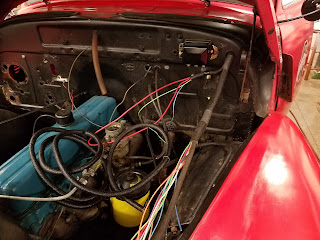
As with most of these old trucks, time and previous owners have not been kind on the electrical systems.  Sure, it all works most of the time, but try diagnosing an issue or wire up another circuit is next to impossible.  Usually, the best thing to do is to cut it all out and start from scratch.


This was my personal favorite....14-4 machine cord wire for the headlights.


Here is the main feed for the headlights. This old cloth covered wire has power to it all the time.  The insulation was literally falling off in my hands as I touched it.  As you can see, some other circuit was "spliced" into it with copious amounts of electrical tape.


After a little time spent cutting and pulling, things are so much better...


There is some tidying up that still needs to be done but at least it's manageable now...